I decided to build what had to be one of the first Repstrap Huxleys in the world and this is what I came up with.
 |
| This is my hackley called the Geometric Object Deposition Tool |
I started by creating 2D pictures of the original Huxley STL files using Meshlab.
 |
| Sheet 1 |
 | |
| Sheet 2 |
 | |
| Sheet 3 |
 |
| Sheet 4 |
 |
| Sheet 5 |
I then had to decide which parts were necessary and which were overdesgined simply because they were designed for 3D printing and laser cutting.
Sheet 1,2,4
------------------------------------
I found most of these to be far to complicated due to the bearings and unnecessary if using bushings. I made the green parts originally and found the bars were to close together and made a wider version.
Sheet 3
------------------------------------
The (green) Y-motor mount and idler I found were needed, but now realize the idler is not needed if built like a Prusa. The frog was over desgined and the clamps seemed unneeded.
Sheet5
------------------------------------
The (green) Z-Lead screw bases seemed a must. And the upper Z-clamps were needed but not the lower ones.
Not yet shown
------------------------------------
Vertices are needed.
The build process
----------------------------------------------------------------------------------------------------
I am going to cover the full build process of the vertices only. The rest of the pieces are made in the same way. ( by leaving channels in layers requiring horizontal holes )
Step 1
------------
Acquire wood in sheet form, any thickness up to and including 1/4" / 6mm
Step 2
------------
Test scaling by printing either sheet and compare the motor bolt pattern against your motor.
For 3/16" / 4mm and thicker print 2 copies of pattern 1 and 4 of pattern 2.
For 1/8"/ 3mm and thinner print 3 copies of pattern 2 and 6 of pattern 2.
There will be extra parts being cut and may be needed due to some bad cuts.
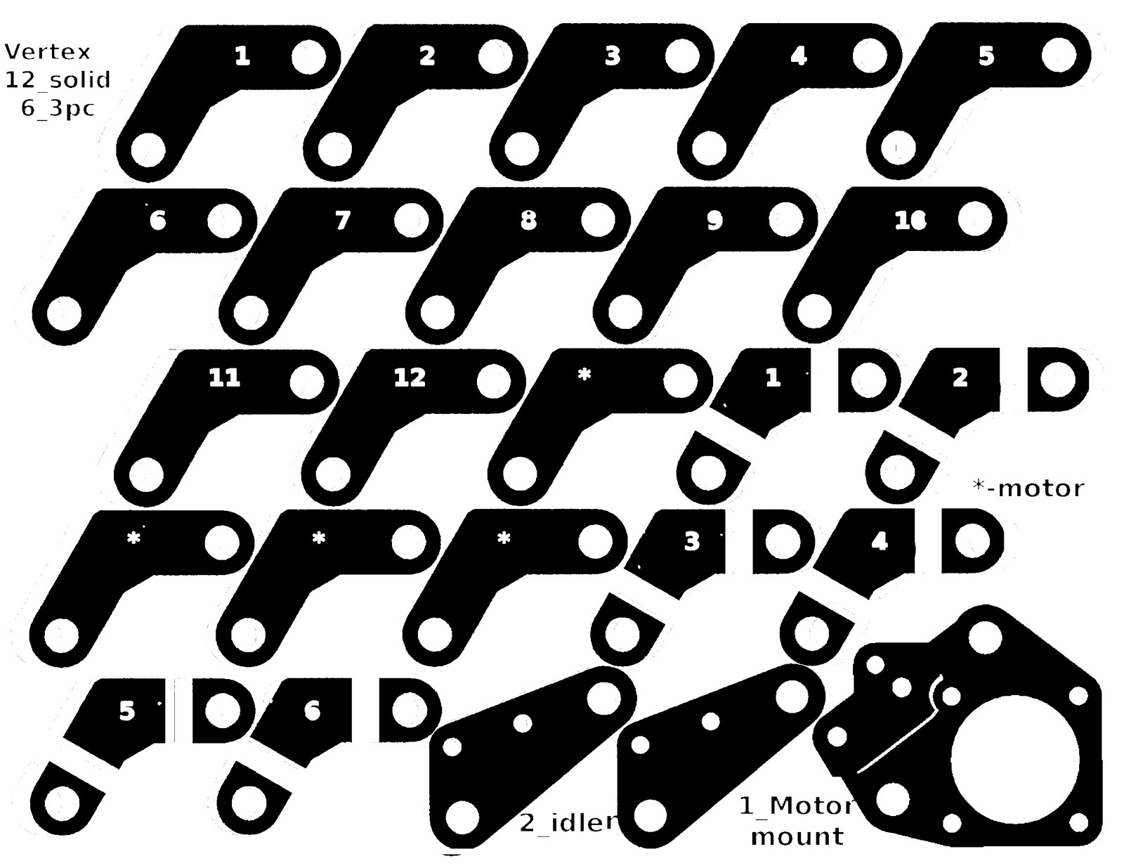 |
| Pattern 1 |
 |
| Pattern 2 |
Step 3
------------
Glue the patterns to the wood.
Step 4
------------
Cut vertices into strips ( I used a friends table saw )
Step 5
------------
Cut vertice strips into separate pieces ( I used a miter box )

Step 6
------------
Refine shape of vertices ( I used a miter box )


I will assume you are using 3/16 / 4mm and thicker from this point on.
If using thinner wood you will need to use more layers.
Step 6
------------
You should now have a big pile of small (roughly cut) pieces ready to be glued together.
Use wood glue to glue the three small pieces from cutting up one of the vertices marked 2 in above pictures between two of the vertices marked 7 in the above picture. Clamp and let dry over night. ( remove pattern from in between layers )
Repeat until you have all the vertices glued together.
Drill all holes one drill size larger than the threaded rod you are using. The resin needs room too.
Step 7
------------
Once the glue has dried its time to drill out the channels left by the cuts in the pieces marked 2 in above picture. Also drill the remaining two holes for the horizontal bars at this time.
Step 8
------------
Using a wood rasp quickly remove the corners and rough/unaligned edges.
Step 9
------------
Prepare the vertices for resin by hanging on a wire or string above a drop cloth or newspaper in a well ventilated space or outside.
Step 10
------------
Mix 125ml (1/2 cup) of your favourite resin ( I use cheap polyester fiberglass resin ) in a disposable container. Apply liberally to all surfaces including the holes. ( I dipped mine and then hung them ) Let dry ( time depends on resin and mix ratio )
Step 11
------------
Re-drill all holes.

Z-leadscrew bases
A few notes on building the lead screw bases.
The bearing holes do not need the notches.
The square holes are just to reduce plastic when printing.
Only the motor needs to be recessed the rest can be a big block.
I didn't use the lower Z-bar clamps, instead I drilled a hole in the top and pushed the z-bar into it.
To align the bearing I glued the bearing support on after assembly of the machine.

Y-motor mount
I used one Y-motor mount from the pattern glued to two Y-idler pieces as the motor mount with a little modification of the idler pieces to clear the motor.

Y-carriage
Not much to say here. It consists of four bronze bushing (2 long ones cut in half) epoxied to some scraps of wood and abs sheet. My bed is made of 1/8" acrylic and is attached using four machine screws on top of four springs to make levelling easy.

X-motor/idler (Z-carriages)
I built the ones included in the pattern but found the bars to be to close together for any reasonable X-carriage and hotend.
I then proceeded to build a wider version of them. They use two bronze bushings on each side epoxied directly to the Z-carriages. I assembled them using wood glue and then coated the bars with Vaseline before epoxying the bushing to the Z-carriage while the bars were in place for alignment. Once the epoxy was dry I glued cardboard on to enclose the space between the bushings (see pic). I then proceeded to fill the cavity with Vaseline before coating the entire piece with resin. ( be sure not to get any resin in the bushings )

They were designed to have the idlers and motor mounted in the same orientation as a real Huxley or Mendel. After designing a new hotend which did not fit in my original X-carriage I decided to change the idler and motor to the Prusa orientation of being horizontal. With this being said I do not have much in the way of design for them but will be more than happy to try and answer questions.
X-carriage
My original X-carriage used bronze bushings like my other axis but was to small for my new hotend and. Having to replace it I choose to use bearings instead of bushing because I didn't want to take apart the entire stage and I didn't have the ability to print bushings yet.
The new X-carriage is made from:
1 - heatsink
4 - 1"/25mm stanley corner braces (30-3005)
4 - 1"/25mm stanley corner braces (30-3005) flattened out to be 2"/50mm flat bars
4 - 1/4" x 2-1/2" carriage bolts
12 - 1/4" nuts
10 - 608 skate bearings
10 - 1/4" i.d. 5/16" o.d. sleeves from old skates
misc washers

Hotend
I built a nichrome hotend and a surface mount power resistor hotend with 1/4" o.d. ptfe tube running through a stainless tube. Neither performed properly due to the long thermal transition zone which increased the force to extrude. I settled on a design based on Nophead's plumbstruder.
Much like the rest of you out there PEEK is not an option for me so I had to come up with something else to use. I settled on two layers of PCB material with the copper removed (old circuit board) in place of the PEEK in Nopheads design. The next issue was not having high temp solder or the ability to braze it together so my design uses set screws which have the bonus effect of reducing thermal conductivity between the cap and barrel. I had a piece of stainless tubing that fit the teflon from ultimachine perfectly so no machining was needed. All I had to do was find a cap that fit and after a few minutes in Home Depot I found a 1/2" brass pipe cap that only needed the threads removed to fit. This was achieved by using a 3/4" step drill backwards with the shank through a hole drilled in the center of the cap. The cap is held to the tube using three 10-32 screws. The hotend itself is pressed into the heatsink/X-carriage and also has four set screws.

The holes were drilled in the brass pipe cap to reduce it thermal mass and to save weight.
The resistor is the same one Nophead recommends and Ultimachine sells. Its held in with ceramic exhaust pipe sealant available at auto parts stores. I used 1/4" brass bolts with a 3.5mm hole down the center, I drilled 6 or 7 to get 2 or 3 useable ones and even then they were easy to break. I would recommend using a larger bolt if available. My tip is a 1/4" acorn nut with a .4???mm hole drilled in it. ( 5.5mm after extrusion w/swell )
Notes of interest
All work other than the table sawing were done in my kitchen or patio in the case of the resin.
Precision in drilling the holes is not as important as others would have you think. The use of threaded rods allows for tweaking the shape.
All holes were drilled using a cordless hand drill.
The hollow brass bolts were made by spinning the bolt in the drill while holding the drill bit with pliers. (0.4mm hole drilled while holding the bit in my fingers)
My machine uses 3/8" rods and bushings for Z salvaged from an old printer. It uses 8mm rods and bushings for X salvaged from old printers. The Y stage uses 5/16" steel rod from homedepot and bronze bushings.
All my motors are salvaged from printers and have different pulleys, belts and torque/amperage.
The 3/8" Z rods make it stiffer than my sae Prusa.
The X rods are attached using wire clips like these in the same way as Prusa does.
My extruder is based on Wades and is built similar to this. (see my comments)
They now have a newly designed flyer that they want to use for a special promotion. They want to start with a small run of high-quality color flyers, and need the option to print more at a moment's notice. The promotion lasts for three weeks. renting impresoras sevilla
ReplyDelete